PDF Preview
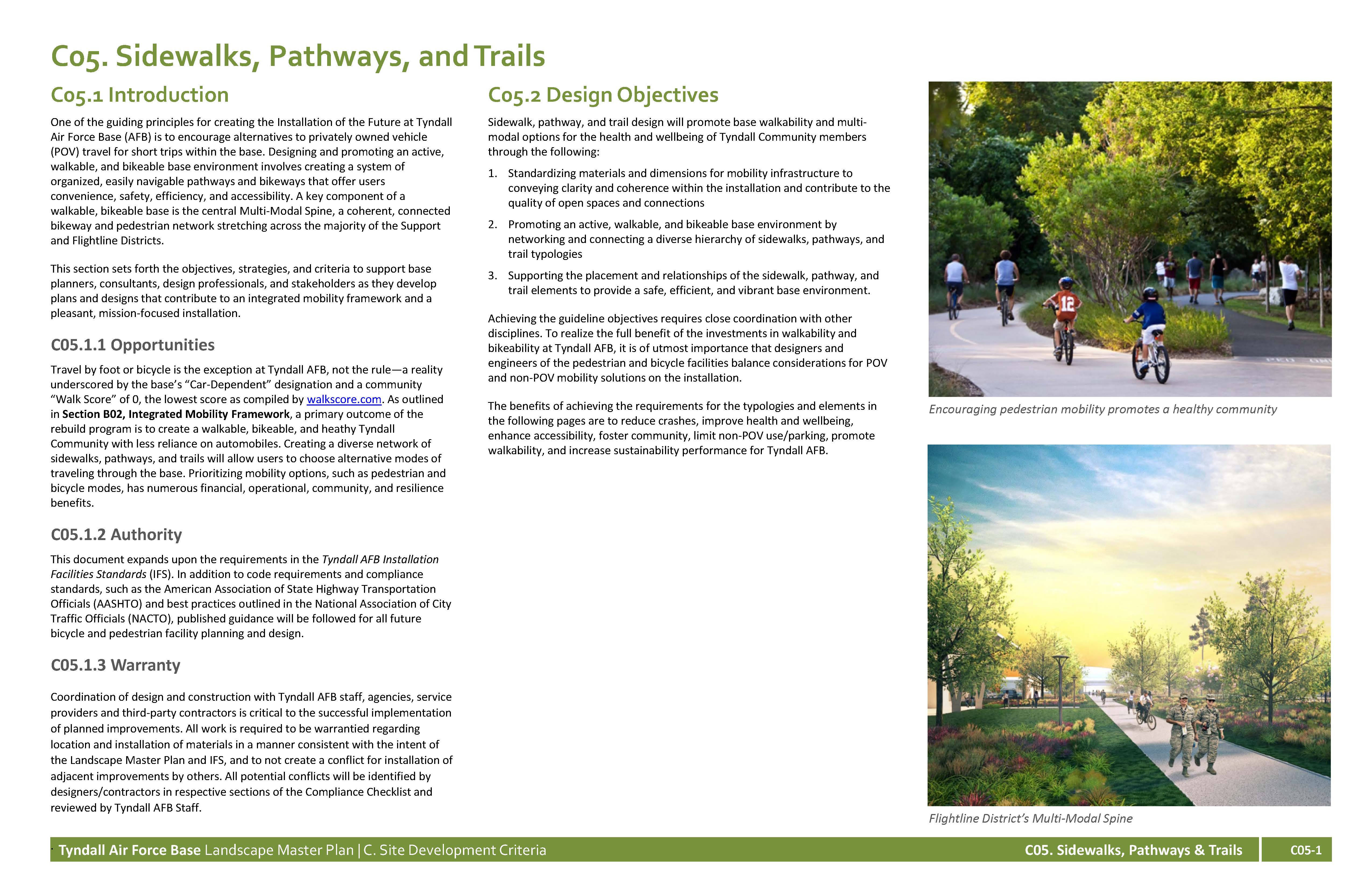
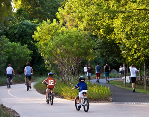
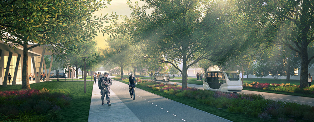
One of the guiding principles for creating the Installation of the Future at Tyndall Air Force Base (AFB) is to encourage alternatives to privately owned vehicle (POV) travel for short trips within the base. Designing and promoting an active, walkable, and bikeable base environment involves creating a system of organized, easily navigable pathways and bikeways that offer users convenience, safety, efficiency, and accessibility. A key component of a walkable, bikeable base is the central Multi-Modal Spine, a coherent, connected bikeway and pedestrian network stretching across the majority of the Support and Flightline Districts.
This section sets forth the objectives, strategies, and criteria to support base planners, consultants, design professionals, and stakeholders as they develop plans and designs that contribute to an integrated mobility framework and a pleasant, mission-focused installation.
Travel by foot or bicycle is the exception at Tyndall AFB, not the rule—a reality underscored by the base’s “Car-Dependent” designation and a community “Walk Score” of 0, the lowest score as compiled by walkscore.com. As outlined in Section B02, Integrated Mobility Framework, a primary outcome of the rebuild program is to create a walkable, bikeable, and heathy Tyndall Community with less reliance on automobiles. Creating a diverse network of sidewalks, pathways, and trails will allow users to choose alternative modes of traveling through the base. Prioritizing mobility options, such as pedestrian and bicycle modes, has numerous financial, operational, community, and resilience benefits.
This document expands upon the requirements in the Tyndall AFB Installation Facilities Standards (IFS). In addition to code requirements and compliance standards, such as the American Association of State Highway Transportation Officials (AASHTO) and best practices outlined in the National Association of City Traffic Officials (NACTO), published guidance will be followed for all future bicycle and pedestrian facility planning and design.
Coordination of design and construction with Tyndall AFB staff, agencies, service providers and third-party contractors is critical to the successful implementation of planned improvements. All work is required to be warrantied regarding location and installation of materials in a manner consistent with the intent of the Landscape Master Plan and IFS, and to not create a conflict for installation of adjacent improvements by others. All potential conflicts will be identified by contractors in respective sections of the Compliance Checklist and reviewed by Tyndall AFB Staff.
Sidewalk, pathway, and trail design will promote base walkability and multi-modal options for the health and wellbeing of Tyndall Community members through the following:
Achieving the guideline objectives requires close coordination with other disciplines. To realize the full benefit of the investments in walkability and bikeability at Tyndall AFB, it is of utmost importance that designers and engineers of the pedestrian and bicycle facilities balance considerations for POV and non-POV mobility solutions on the installation.
The benefits of achieving the requirements for the typologies and elements in the following pages are to reduce crashes, improve health and wellbeing, enhance accessibility, foster community, limit non-POV use/parking, promote walkability, and increase sustainability performance for Tyndall AFB.
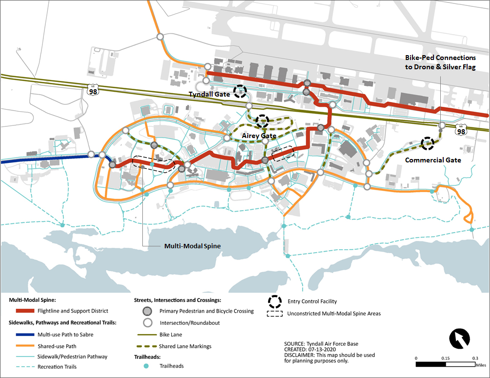
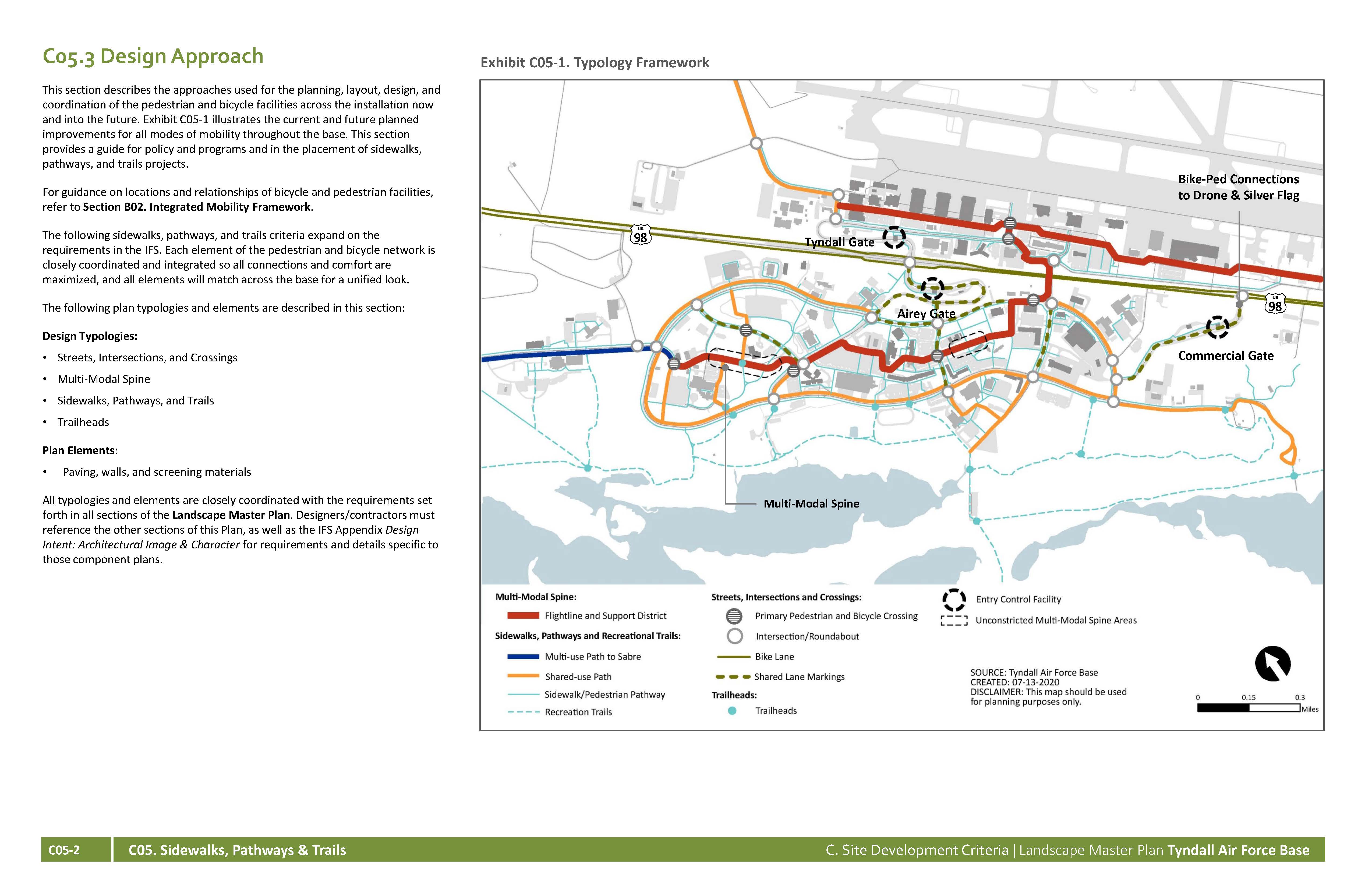
This section describes the approaches used for the planning, layout, design, and coordination of the pedestrian and bicycle facilities across the installation now and into the future. Exhibit C05-1 illustrates the current and future planned improvements for all modes of mobility throughout the base. This section provides a guide for policy and programs and in the placement of sidewalks, pathways, and trails projects.
For guidance on locations and relationships of bicycle and pedestrian facilities, refer to Section B02. Integrated Mobility Framework.
The following sidewalks, pathways, and trails criteria expand on the requirements in the IFS. Each element of the pedestrian and bicycle network is closely coordinated and integrated so all connections and comfort are maximized, and all elements will match across the base for a unified look.
The following plan typologies and elements are described in this section:
Design Typologies:
Plan Elements:
All typologies and elements are closely coordinated with the requirements set forth in all sections of the Landscape Master Plan. Designers must reference the other sections of this Plan, as well as the IFS Appendix Design Intent: Architectural Image & Character for requirements and details specific to those component plans.
Many systems—landscaping, lighting, signage, site design and furnishing and stormwater management—must function together to create Tyndall AFB’s network of sidewalks, pathways, and trails. The typologies discussed in this section describe the unique features that create a safe, accessible, and integrated mobility system.
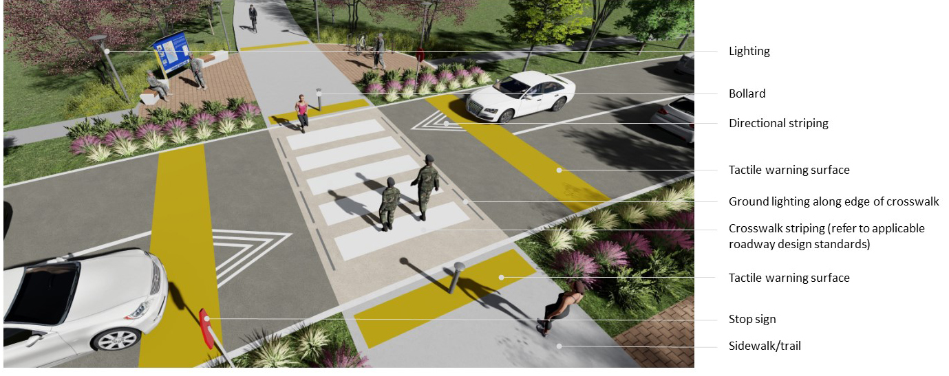
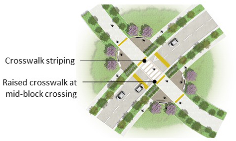
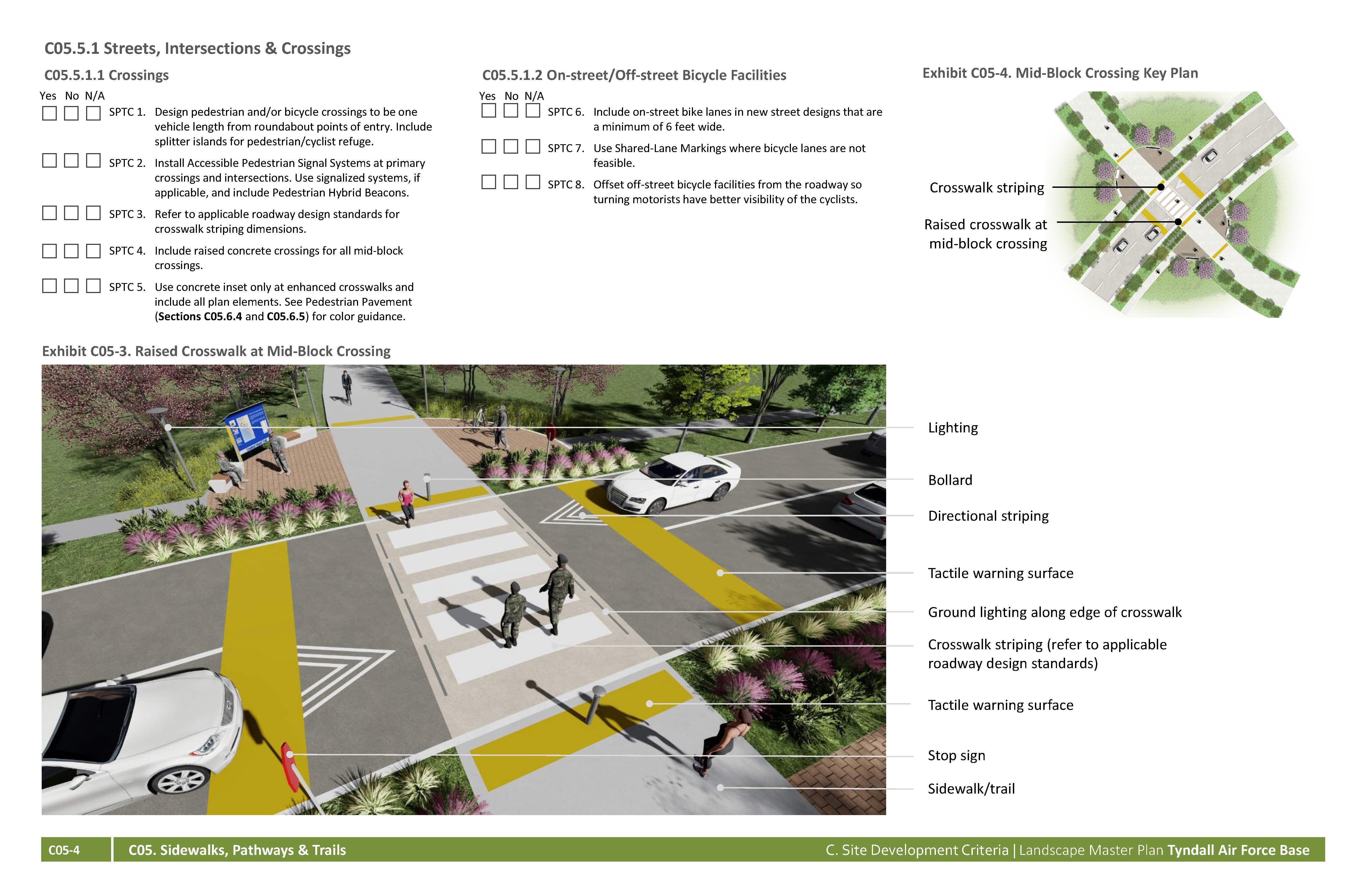
The base’s roadways are designed to accommodate all modes of transportation, with sidewalks and shared-use paths separated from the motorized vehicle lanes by medians, landscape buffers, or drainage swales. To foster a community that chooses walking or biking over driving, safety is a primary concern, especially where sidewalks and pathways cross streets, intersections, and roundabouts. Roadway designs include in-pavement lighting in lieu of traditional traffic signals, tactile warning surfaces and ramps as required by Architectural Barriers Act (ABA) criteria, and pavement markings on roadway shoulders to indicate dedicated bicycle lanes. Painted or concrete paver crosswalks clearly delineate pedestrian crossing zones. Enhanced pavements at roadway corners not only provide a visual cue to pedestrians, but also make pedestrian areas more visible to drivers.
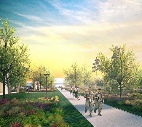
The Multi-Modal Spine links the Support and Flightline Districts and provides distinct facilities for pedestrians, bicyclists, and operator-driven shuttles and eventual autonomous vehicles, providing the Tyndall Community ready access to residential, mission-related, dining, and entertainment facilities all within a 10- to 15-minute walk or bike ride. Because the Multi-Modal Spine accommodates various users, site amenities need to provide lighting, wayfinding signage, accessible features, and site furnishings that are appropriate for its many uses. In addition, the Multi-Modal Spine provides access between parking areas and buildings, so antiterrorism setbacks and landscaped medians must be incorporated in designs.
The base’s diverse mobility network includes sidewalk, pathway, and trail components that encourage a walkable and bikeable installation. Throughout the base, shared-use paths provided combined facilities for bicyclists and pedestrians with the same level of connectivity. Not only do these typologies promote a safe and active culture at Tyndall AFB, they also add to the base’s resiliency. Pervious pavements are incorporated when applicable to manage stormwater. Trails and boardwalks provide access to the Coastal Zone’s beautiful natural areas in a way that does not impact the sensitive environment.
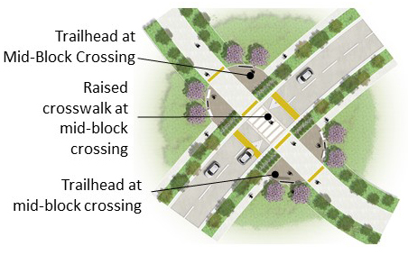
Small trailheads are provided where trails terminate at or cross intersections or roundabouts. These areas are set back form the sidewalk and include lighting, site furnishings, and secondary-type wayfinding signage to provide a restful, informative space.
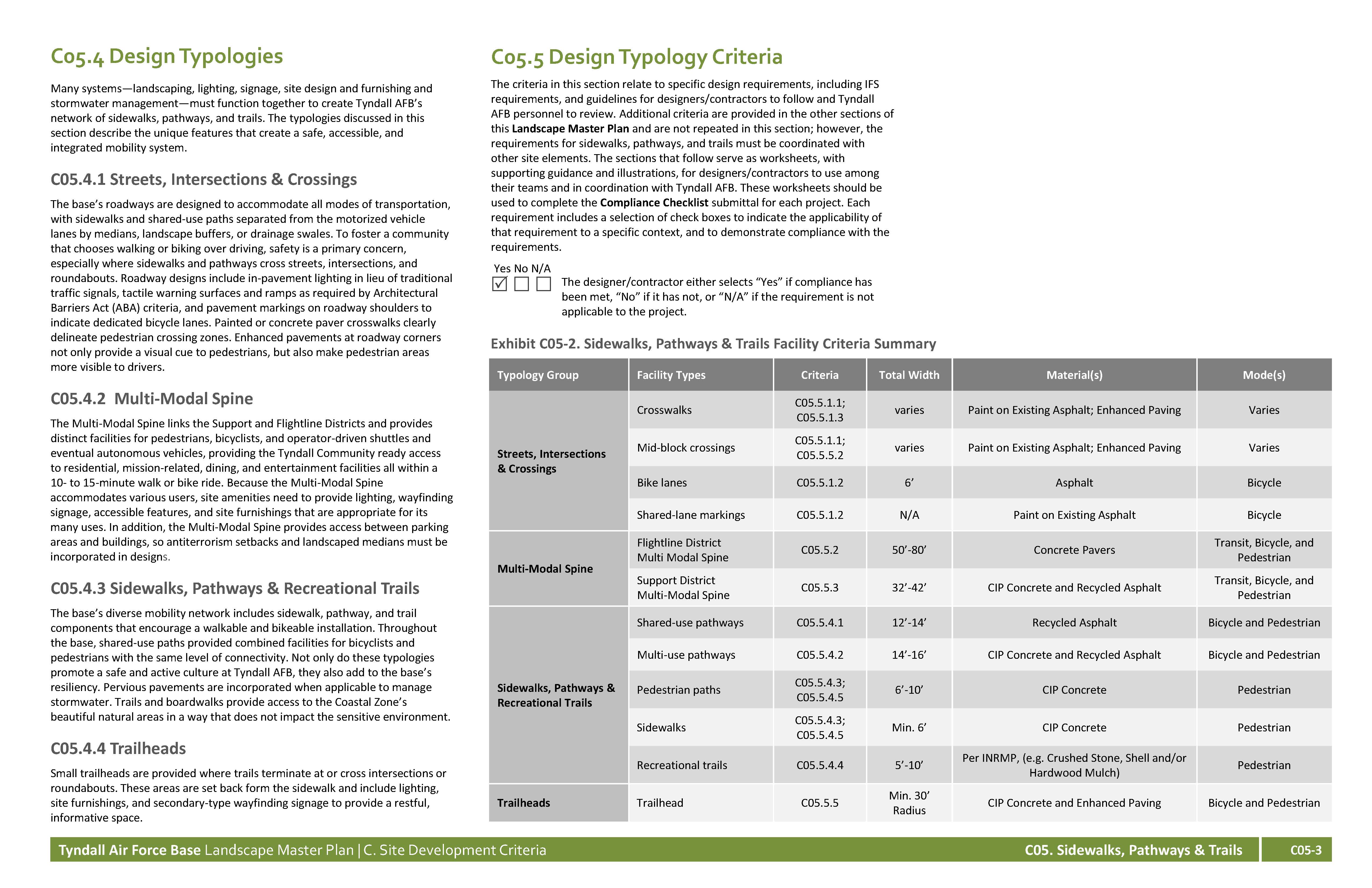
The criteria in this section relate to specific design requirements, including IFS requirements, and guidelines for contractors to follow and Tyndall AFB personnel to review. Additional criteria are provided in the other sections of this Landscape Master Plan and are not repeated in this section; however, the requirements for sidewalks, pathways, and trails must be coordinated with other site elements. The sections that follow serve as worksheets, with supporting guidance and illustrations, for contractors to use among their teams and in coordination with Tyndall AFB. These worksheets should be used to complete the Compliance Checklist submittal for each project. Each requirement includes a selection of check boxes to indicate the applicability of that requirement to a specific context, and to demonstrate compliance with the requirements.
Yes No NA The designer/contractor either selects “Yes” if compliance has been met, “No” if it has not, or “N/A” if the requirement is not applicable to the project.
| Typology Group | Facility Types | Criteria | Total Width | Material(s) | Mode(s) |
|---|---|---|---|---|---|
| Streets, Intersections & Crossings | Crosswalks | C05.5.1.1; C05.5.1.3 | varies | Paint on Existing Asphalt; Enhanced Paving | Varies |
| Mid-block crossings | C05.5.1.1; C05.5.5.2 | varies | Paint on Existing Asphalt; Enhanced Paving | Varies | |
| Bike lanes | C05.5.1.2 | 6’ | Asphalt | Bicycle | |
| Shared-lane markings | C05.5.1.2 | N/A | Paint on Existing Asphalt | Bicycle | |
| Multi-Modal Spine | Flightline District Multi Modal Spine | C05.5.2 | 50’-80’ | Concrete Pavers | Transit, Bicycle, and Pedestrian |
| Support District Multi-Modal Spine | C05.5.3 | 32’-42’ | CIP Concrete and Recycled Asphalt | Transit, Bicycle, and Pedestrian | |
| Sidewalks, Pathways & Recreational Trails | Shared-use pathways | C05.5.4.1 | 12’-14’ | Recycled Asphalt | Bicycle and Pedestrian |
| Multi-use pathways | C05.5.4.2 | 14’-16’ | CIP Concrete and Recycled Asphalt | Bicycle and Pedestrian | |
| Pedestrian paths | C05.5.4.3; C05.5.4.5 | 6’-10’ | CIP Concrete | Pedestrian | |
| Sidewalks | C05.5.4.3; C05.5.4.5 | Min. 6’ | CIP Concrete | Pedestrian | |
| Recreational trails | C05.5.4.4 | 5’-10’ | Per INRMP, (e.g. Crushed Stone, Shell and/or Hardwood Mulch) | Pedestrian | |
| Trailheads | Trailhead | C05.5.5 | Min. 30’ Radius | CIP Concrete and Enhanced Paving | Bicycle and Pedestrian |
Yes No NA
SPTC 1. Design pedestrian and/or bicycle crossings to be one vehicle length from roundabout points of entry. Include splitter islands for pedestrian/cyclist refuge.
SPTC 2. Install Accessible Pedestrian Signal Systems at primary crossings and intersections. Use signalized systems, if applicable, and include Pedestrian Hybrid Beacons.
SPTC 3. Refer to applicable roadway design standards for crosswalk striping dimensions.
SPTC 4. Include raised concrete crossings for all mid-block crossings.
SPTC 5. Use concrete inset only at enhanced crosswalks and include all plan elements. See Pedestrian Pavement (Sections C05.6.4 and C05.6.5) for color guidance.
Yes No NA
SPTC 6. Include on-street bike lanes in new street designs that are a minimum of 6 feet wide.
SPTC 7. Use Shared-Lane Markings where bicycle lanes are not feasible.
SPTC 8. Offset off-street bicycle facilities from the roadway so turning motorists have better visibility of the cyclists.
Yes No NA
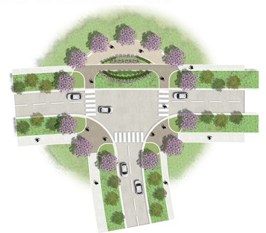
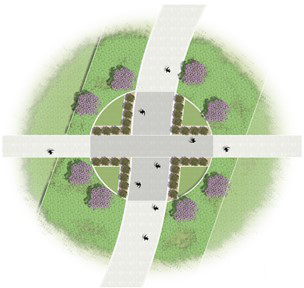
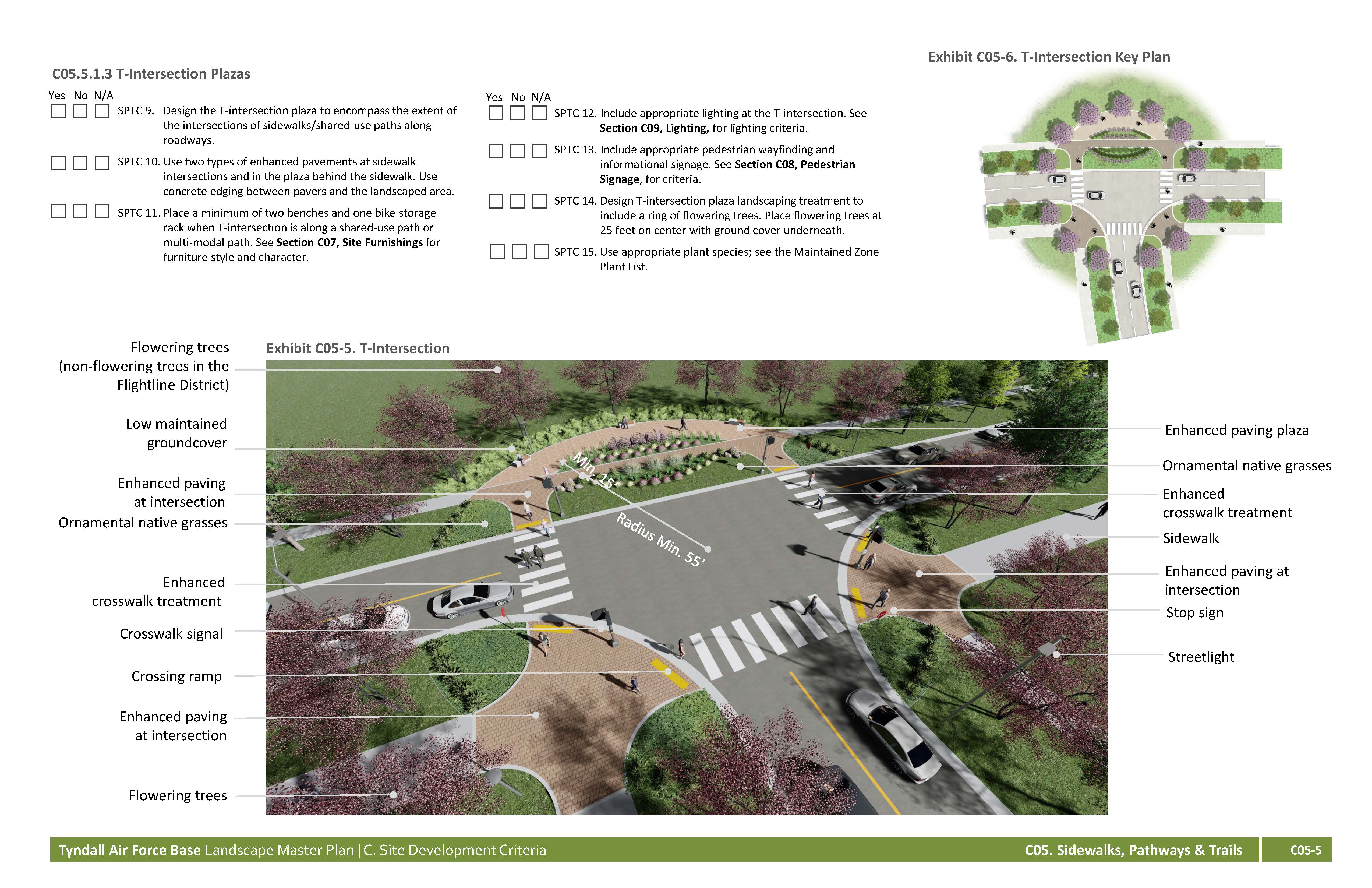
SPTC 9. Design the T-intersection plaza to encompass the extent of the intersections of sidewalks/shared-use paths along roadways.
SPTC 10. Use two types of enhanced pavements at sidewalk intersections and in the plaza behind the sidewalk. Use concrete edging between pavers and the landscaped area.
SPTC 11. Place a minimum of two benches and one bike storage rack when T-intersection is along
a shared-use path or
multi-modal path. See Section C07, Site Furnishings for furniture style
and character.
SPTC 12. Include appropriate lighting at the T-intersection. See Section C09, Lighting, for lighting criteria.
SPTC 13. Include appropriate pedestrian wayfinding and informational signage. See Section C08, Pedestrian Signage, for criteria.
SPTC 14. Design T-intersection plaza landscaping treatment to include a ring of flowering trees. Place flowering trees at 25 feet on center with ground cover underneath.
SPTC 15. Use appropriate plant species; see the Maintained Zone Plant List.
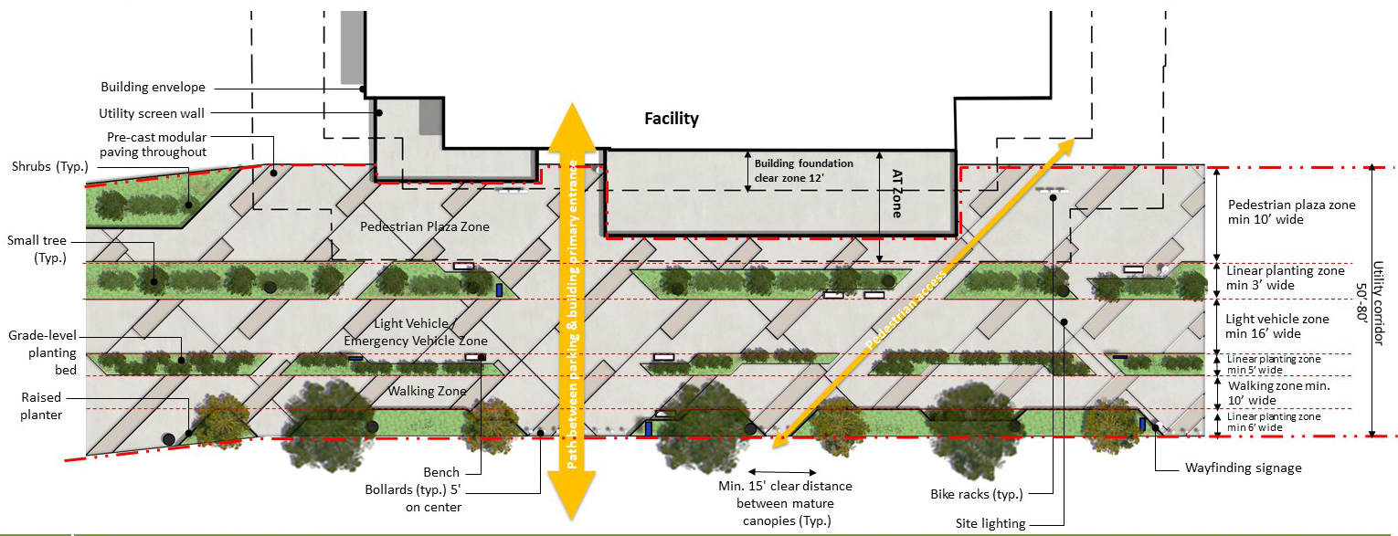
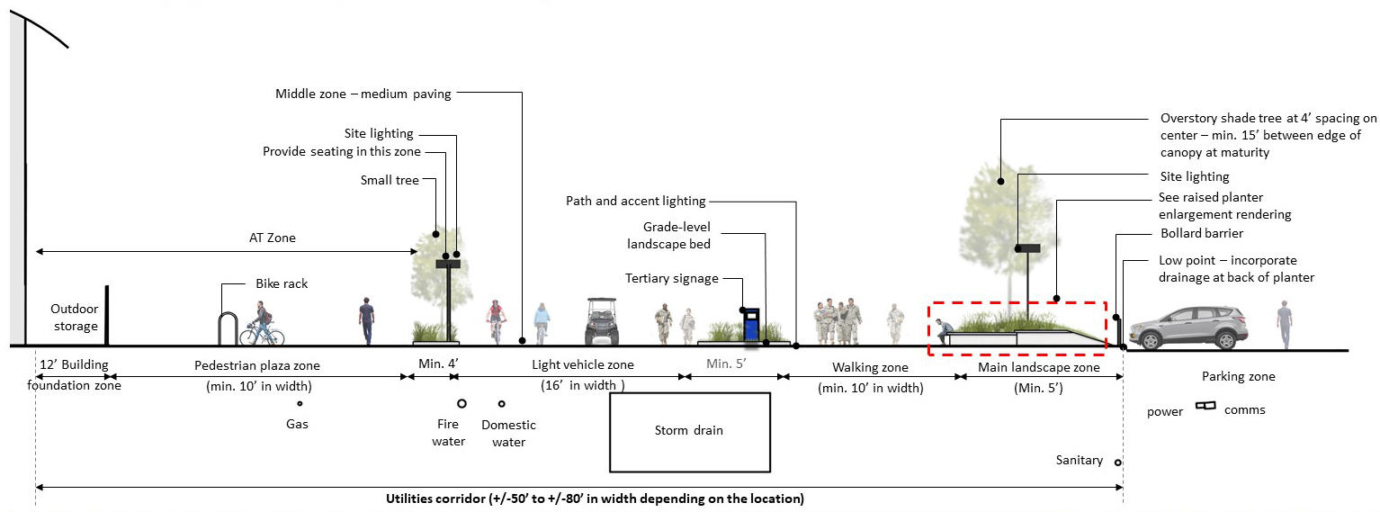
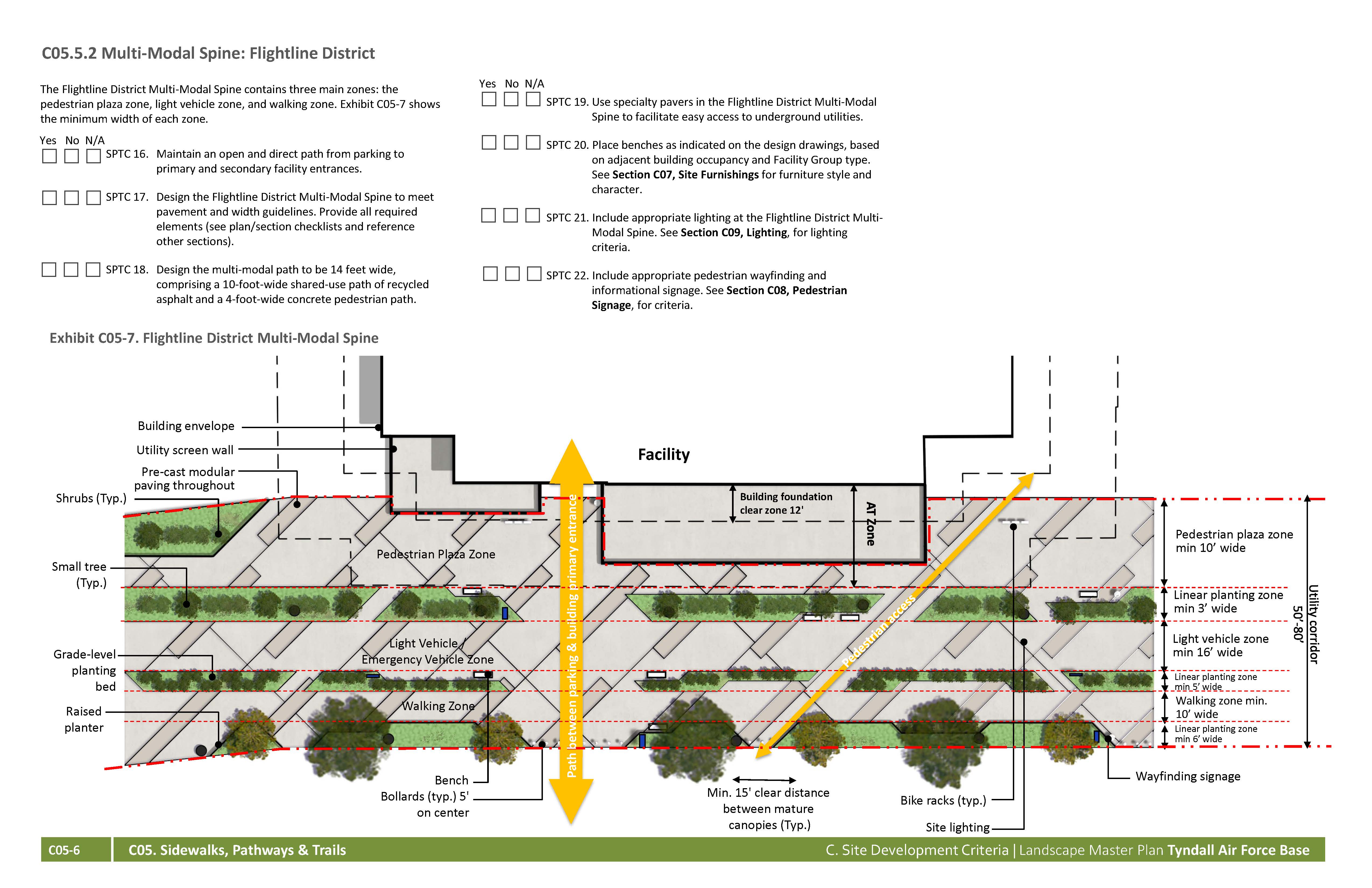
The Flightline District Multi-Modal Spine contains three main zones: the pedestrian plaza zone, light vehicle zone, and walking zone. Exhibit C05-7 shows the minimum width of each zone.
Yes No NA
SPTC 16. Maintain an open and direct path from parking to primary and secondary facility entrances.
SPTC 17. Design the Flightline District Multi-Modal Spine to meet pavement and width guidelines. Provide all required elements (see plan/section checklists and reference other sections).
SPTC 18. Design the multi-modal path to be 14 feet wide, comprising a 10-foot-wide shared-use path of recycled asphalt and a 4-foot-wide concrete pedestrian path.
SPTC 19. Use specialty pavers in the Flightline District Multi-Modal Spine to facilitate easy access to underground utilities.
SPTC 20. Place benches as indicated on the design drawings, based on adjacent building occupancy and Facility Group type. See Section C07, Site Furnishings for furniture style and character.
SPTC 21. Include appropriate lighting at the Flightline District Multi-Modal Spine. See Section C09, Lighting, for lighting criteria.
SPTC 22. Include appropriate pedestrian wayfinding and informational signage. See Section C08, Pedestrian Signage, for criteria.
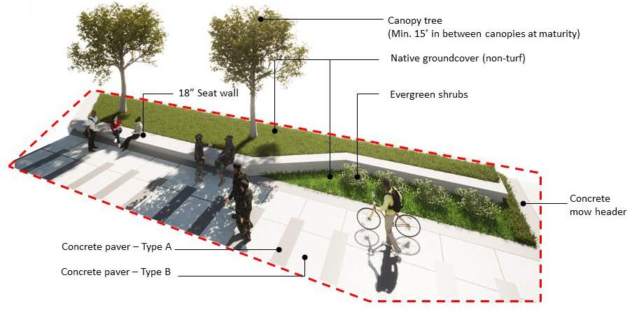
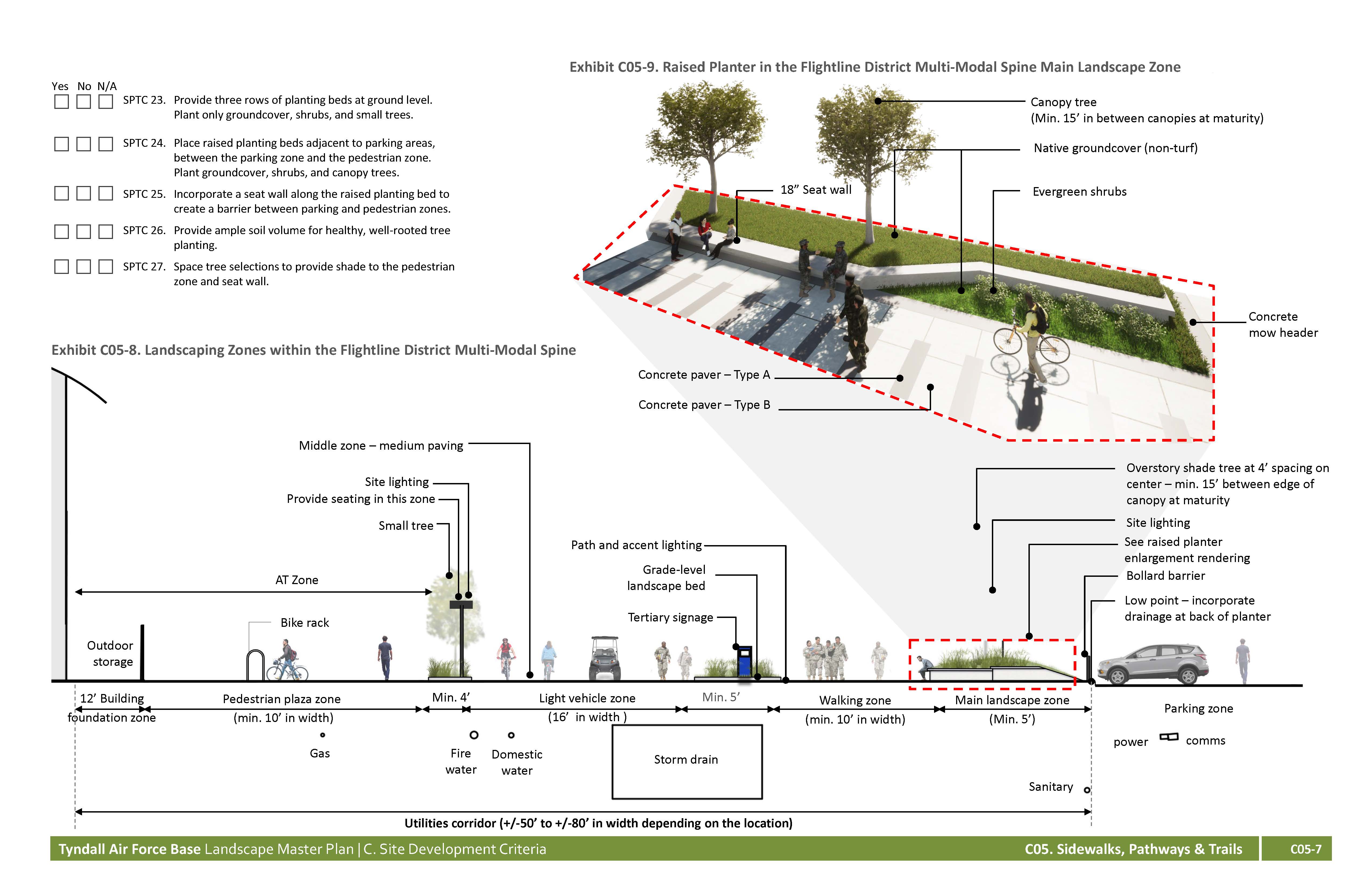
SPTC 23. Provide three rows of planting beds at ground level. Plant only groundcover, shrubs, and small trees.
SPTC 24. Place raised planting beds adjacent to parking areas, between the parking zone and the pedestrian zone. Plant groundcover, shrubs, and canopy trees.
SPTC 25. Incorporate a seat wall along the raised planting bed to create a barrier between parking and pedestrian zones.
SPTC 26. Provide ample soil volume for healthy, well-rooted tree planting.
SPTC 27. Space tree selections to provide shade to the pedestrian zone and seat wall.
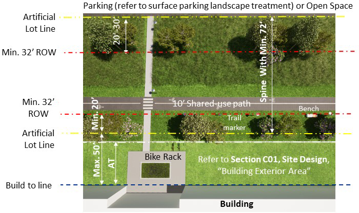
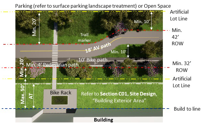
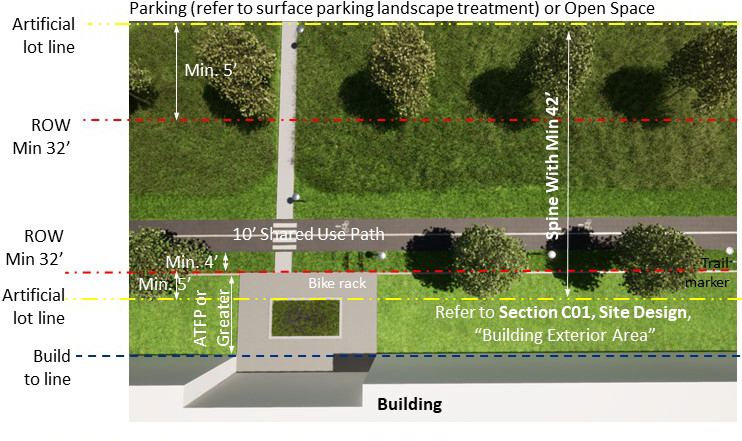
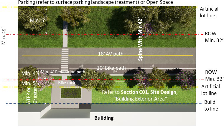
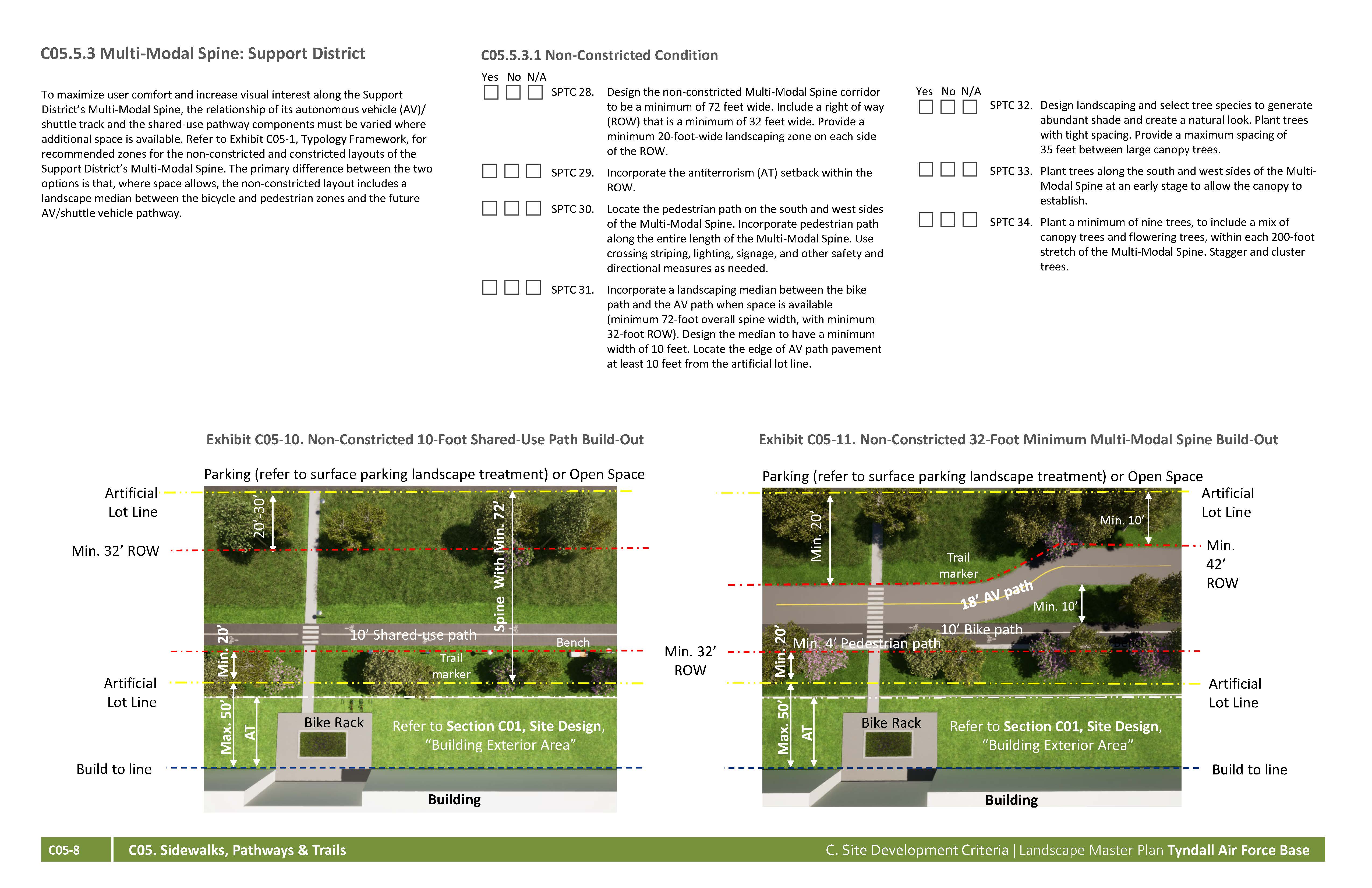
To maximize user comfort and increase visual interest along the Support District’s Multi-Modal Spine, the relationship of its autonomous vehicle (AV)/ shuttle track and the shared-use pathway components must be varied where additional space is available. Refer to Exhibit C05-1, Typology Framework, for recommended zones for the non-constricted and constricted layouts of the Support District’s Multi-Modal Spine. The primary difference between the two options is that, where space allows, the non-constricted layout includes a landscape median between the bicycle and pedestrian zones and the future AV/shuttle vehicle pathway.
Yes No NA
SPTC 28. Design the non-constricted Multi-Modal Spine corridor to be a minimum of 72 feet wide. Include a right of way (ROW) that is a minimum of 32 feet wide. Provide a minimum 20-foot-wide landscaping zone on each side of the ROW.
SPTC 29. Incorporate the antiterrorism (AT) setback within the ROW.
SPTC 30. Locate the pedestrian path on the south and west sides of the Multi-Modal Spine. Incorporate pedestrian path along the entire length of the Multi-Modal Spine. Use crossing striping, lighting, signage, and other safety and directional measures as needed.
SPTC 31. Incorporate a landscaping median between the bike path and the AV path when space is available (minimum 72-foot overall spine width, with minimum 32-foot ROW). Design the median to have a minimum width of 10 feet. Locate the edge of AV path pavement at least 10 feet from the artificial lot line.
SPTC 32. Design landscaping and select tree species to generate abundant shade and create a
natural look. Plant trees with tight spacing. Provide a maximum spacing of
35 feet between
large canopy trees.
SPTC 33. Plant trees along the south and west sides of the Multi-Modal Spine at an early stage to allow the canopy to establish.
SPTC 34. Plant a minimum of nine trees, to include a mix of canopy trees and flowering trees, within each 200-foot stretch of the Multi-Modal Spine. Stagger and cluster trees.
Yes No NA
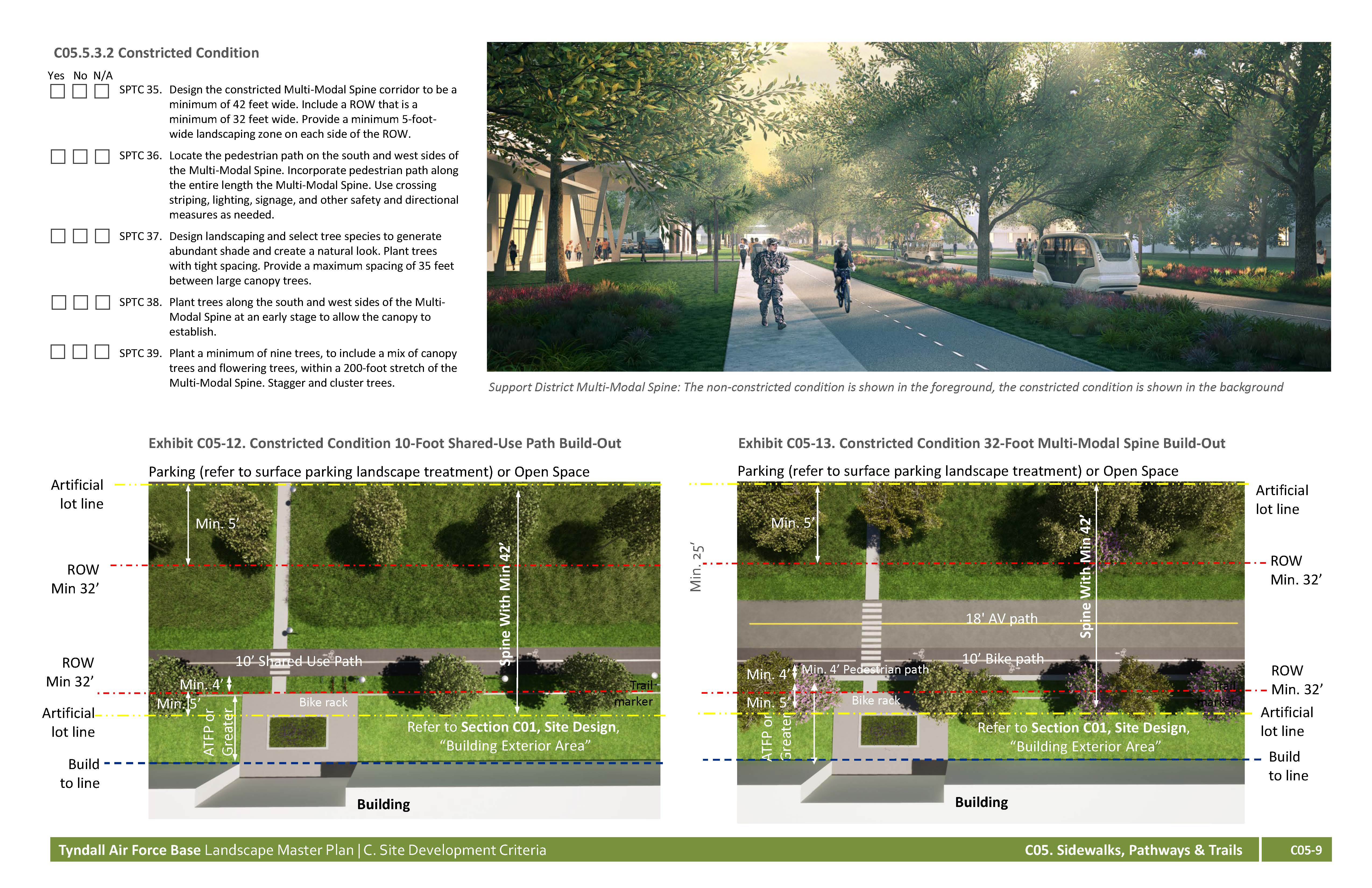
SPTC 35. Design the constricted Multi-Modal Spine corridor to be a minimum of 42 feet wide. Include a ROW that is a minimum of 32 feet wide. Provide a minimum 5-foot-wide landscaping zone on each side of the ROW.
SPTC 36. Locate the pedestrian path on the south and west sides of the Multi-Modal Spine. Incorporate pedestrian path along the entire length the Multi-Modal Spine. Use crossing striping, lighting, signage, and other safety and directional measures as needed.
SPTC 37. Design landscaping and select tree species to generate abundant shade and create a natural look. Plant trees with tight spacing. Provide a maximum spacing of 35 feet between large canopy trees.
SPTC 38. Plant trees along the south and west sides of the Multi-Modal Spine at an early stage to allow the canopy to establish.
SPTC 39. Plant a minimum of nine trees, to include a mix of canopy trees and flowering trees, within a 200-foot stretch of the Multi-Modal Spine. Stagger and cluster trees.
Yes No NA
SPTC 40. Provide code-compliant markings that clearly indicate travel direction and/or distinct bike and pedestrian zones.
SPTC 41. Locate shared-use paths where there is clear visibility between the users and any vehicles.
SPTC 42. Provide a landscape buffer between the shared-use path
and the street.
SPTC 43. Provide code-compliant markings and change of paving materials to clearly indicate travel direction and/or distinct bike and pedestrian zones.
SPTC 44. Locate multi-use paths where there is clear visibility between the users and any vehicles.
SPTC 45. Provide a landscape buffer between the multi-use path
and the street.
SPTC 46. Design sidewalks and pedestrian paths to be a minimum of 6 feet wide and to meet paving requirements.
SPTC 47. Provide trailheads with all required elements (see Section C05.5.5, Trailheads).
SPTC 48. Design recreational or coastal trails to be between 6 and
10 feet wide. Select
INRMP-approved paving materials as defined by ecosystem.
SPTC 49. Design boardwalks and coastal trails to meet all plan element guidelines and applicable codes.
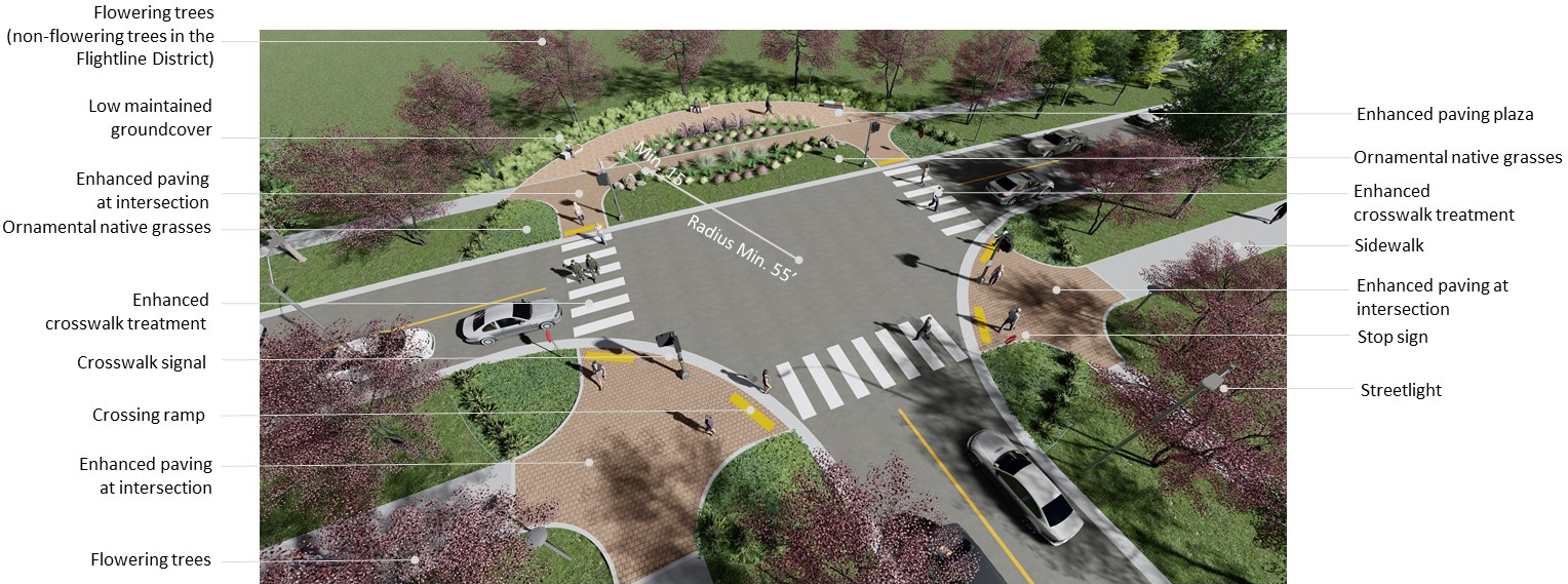
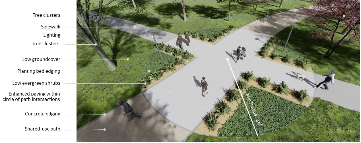
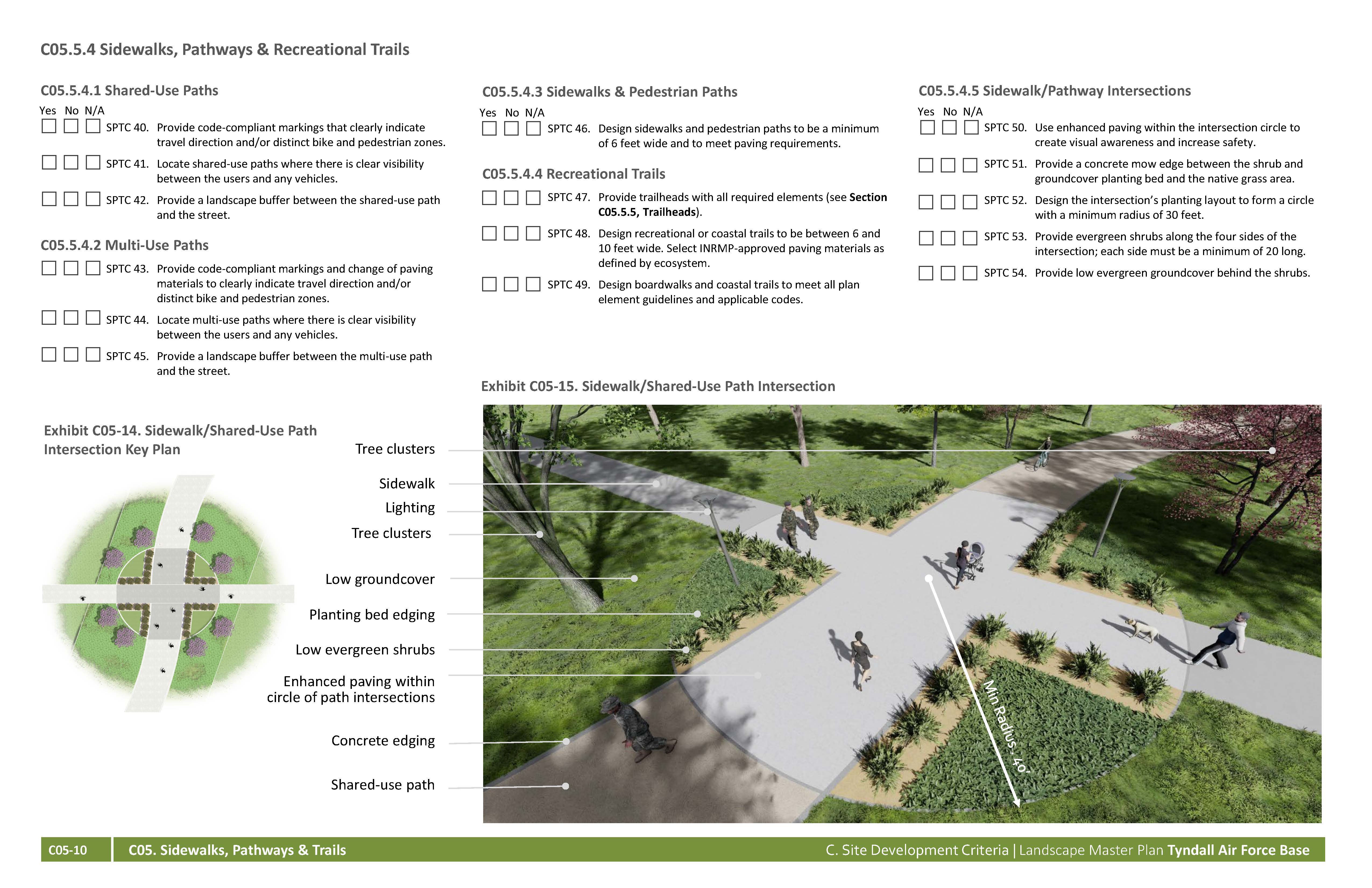
SPTC 50. Use enhanced paving within the intersection circle to create visual awareness and increase safety.
SPTC 51. Provide a concrete mow edge between the shrub and groundcover planting bed and the native grass area.
SPTC 52. Design the intersection’s planting layout to form a circle with a minimum radius of 30 feet.
SPTC 53. Provide evergreen shrubs along the four sides of the intersection; each side must be a minimum of 20 long.
SPTC 54. Provide low evergreen groundcover behind the shrubs.
Yes No NA
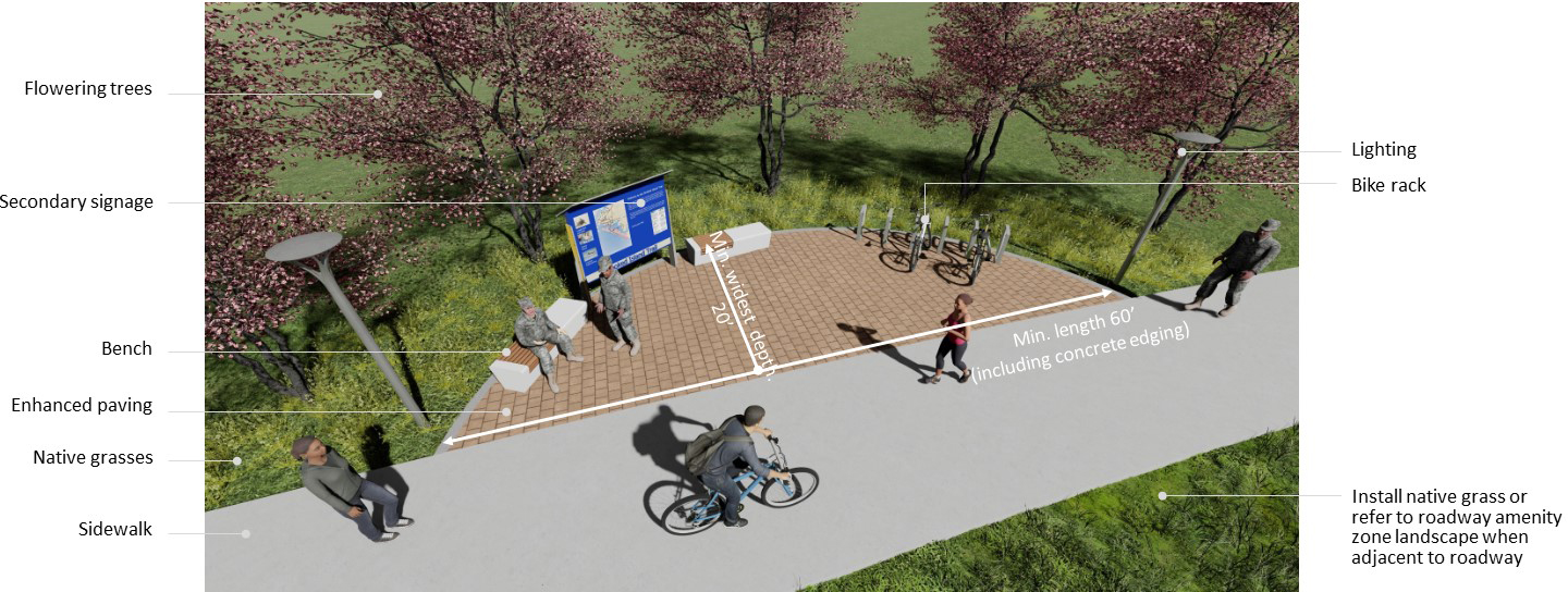
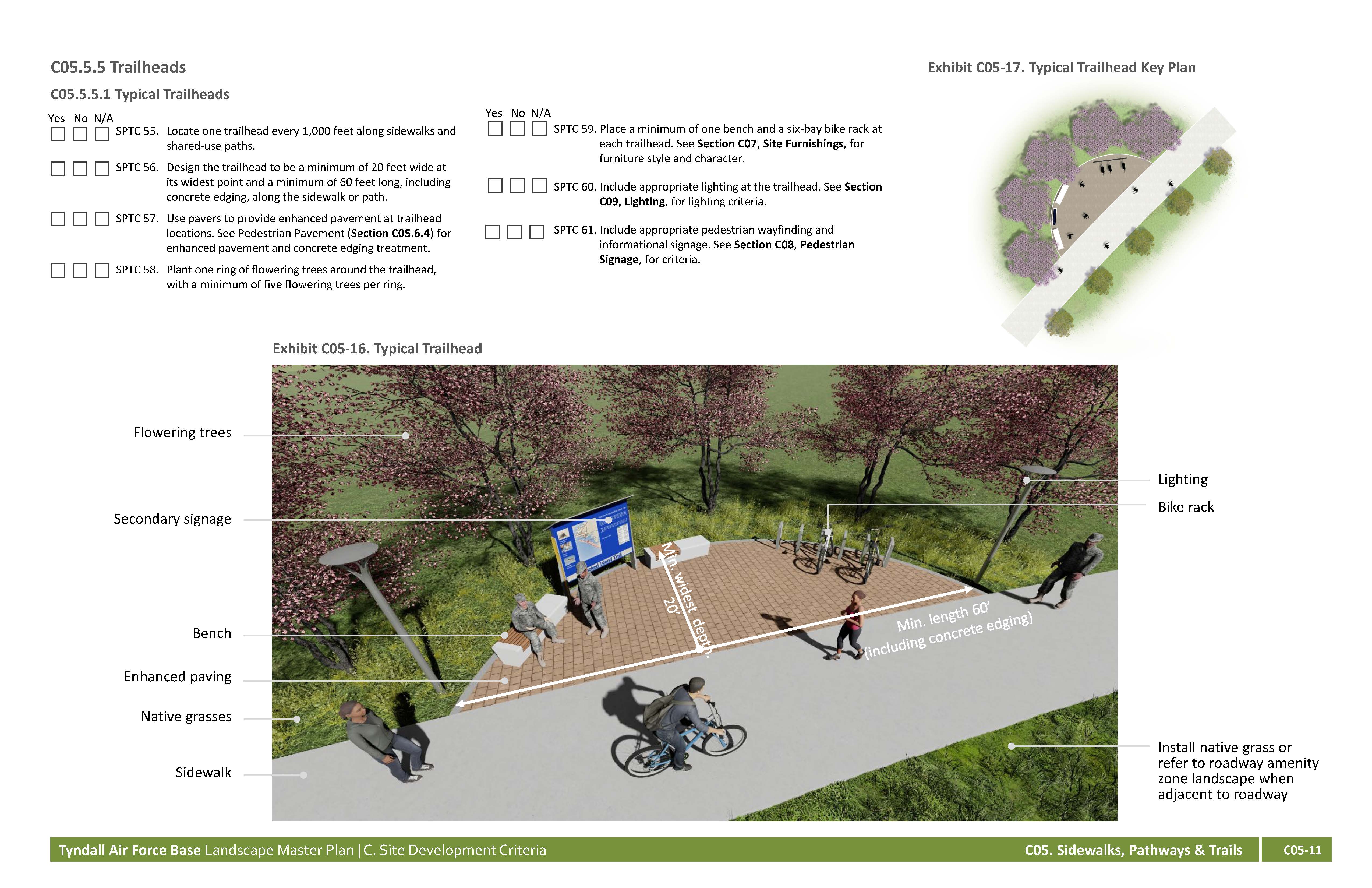
SPTC 55. Locate one trailhead every 1,000 feet along sidewalks and shared-use paths.
SPTC 56. Design the trailhead to be a minimum of 20 feet wide at its widest point and a minimum of 60 feet long, including concrete edging, along the sidewalk or path.
SPTC 57. Use pavers to provide enhanced pavement at trailhead locations. See Pedestrian Pavement (Section C05.6.4) for enhanced pavement and concrete edging treatment.
SPTC 58. Plant one ring of flowering trees around the trailhead, with a minimum of five flowering trees per ring.
SPTC 59. Place a minimum of one bench and a six-bay bike rack at each trailhead. See Section C07, Site Furnishings, for furniture style and character.
SPTC 60. Include appropriate lighting at the trailhead. See Section C09, Lighting, for lighting criteria.
SPTC 61. Include appropriate pedestrian wayfinding and informational signage. See Section C08, Pedestrian Signage, for criteria.
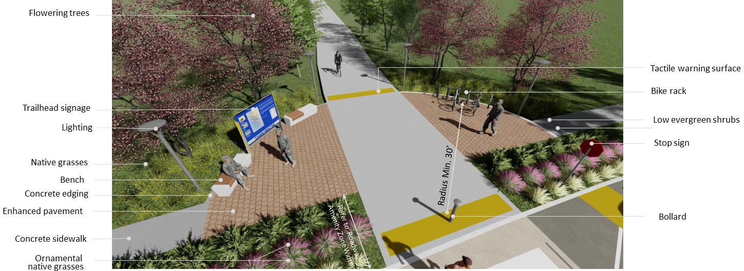
Yes No NA
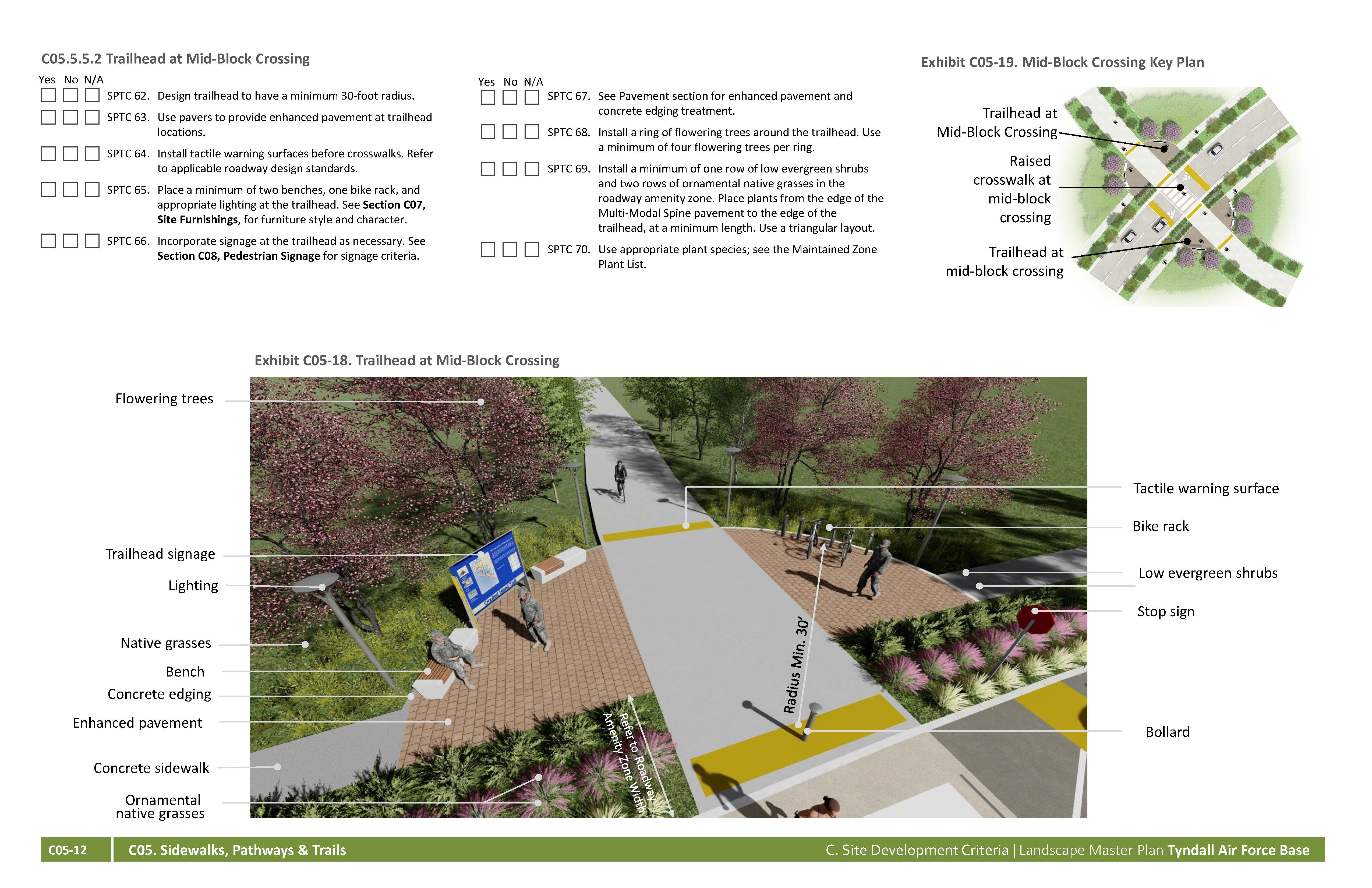
SPTC 62. Design trailhead to have a minimum 30-foot radius.
SPTC 63. Use pavers to provide enhanced pavement at trailhead locations.
SPTC 64. Install tactile warning surfaces before crosswalks. Refer to applicable roadway design standards.
SPTC 65. Place a minimum of two benches, one bike rack, and appropriate lighting at the trailhead. See Section C07, Site Furnishings, for furniture style and character.
SPTC 66. Incorporate signage at the trailhead as necessary. See Section C08, Pedestrian Signage for signage criteria.
SPTC 67. See Pavement section for enhanced pavement and concrete edging treatment.
SPTC 68. Install a ring of flowering trees around the trailhead. Use a minimum of four flowering trees per ring.
SPTC 69. Install a minimum of one row of low evergreen shrubs and two rows of ornamental native grasses in the roadway amenity zone. Place plants from the edge of the Multi-Modal Spine pavement to the edge of the trailhead, at a minimum length. Use a triangular layout.
SPTC 70. Use appropriate plant species; see the Maintained Zone Plant List.
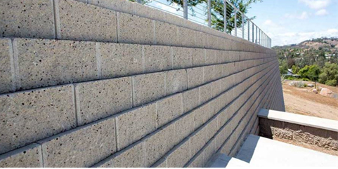
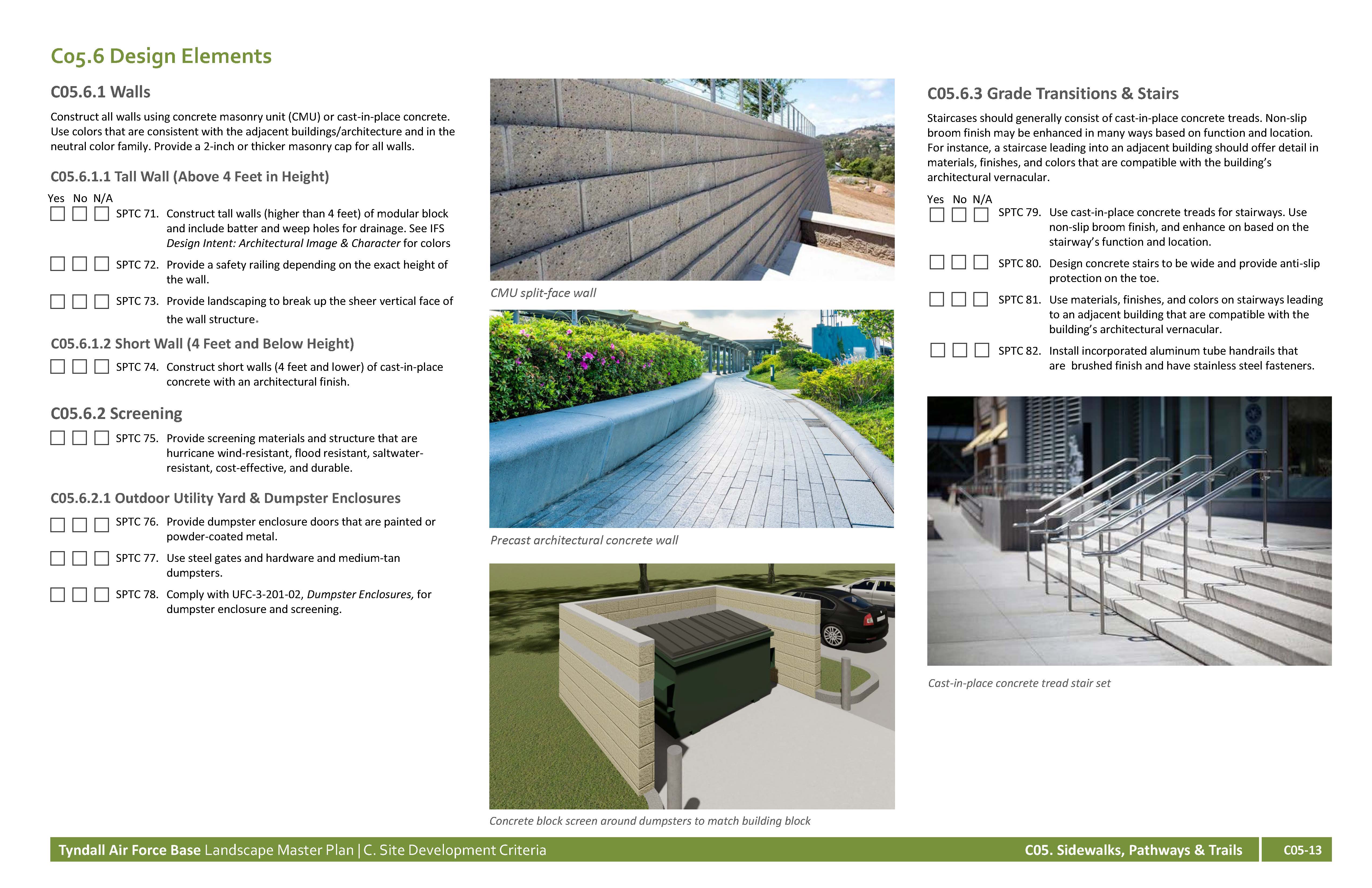
Construct all walls using concrete masonry unit (CMU) or cast-in-place concrete. Use colors that are consistent with the adjacent buildings/architecture and in the neutral color family. Provide a 2-inch or thicker masonry cap for all walls
Yes No NA
SPTC 71. Construct tall walls (higher than 4 feet) of modular block and include batter and weep holes for drainage. See IFS Design Intent: Architectural Image & Character for colors
SPTC 72. Provide a safety railing depending on the exact height of the wall.
SPTC 73. Provide landscaping to break up the sheer vertical face of the wall structure.
Yes No NA
SPTC 74. Construct short walls (4 feet and lower) of cast-in-place concrete with an architectural finish.
Yes No NA
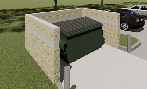
SPTC 75. Provide screening materials and structure that are hurricane wind-resistant, flood resistant, saltwater-resistant, cost-effective, and durable.
Yes No NA
SPTC 76. Provide dumpster enclosure doors that are painted or powder-coated metal.
SPTC 77. Use steel gates and hardware and medium-tan dumpsters.
SPTC 78. Comply with UFC-3-201-02, Dumpster Enclosures, for dumpster enclosure and screening.
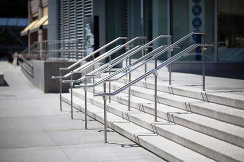
Staircases should generally consist of cast-in-place concrete treads. Non-slip broom finish may be enhanced in many ways based on function and location. For instance, a staircase leading into an adjacent building should offer detail in materials, finishes, and colors that are compatible with the building’s architectural vernacular.
Yes No NA
SPTC 79. Use cast-in-place concrete treads for stairways. Use non-slip broom finish, and enhance on based on the stairway’s function and location.
SPTC 80. Design concrete stairs to be wide and provide anti-slip protection on the toe.
SPTC 81. Use materials, finishes, and colors on stairways leading to an adjacent building that are compatible with the building’s architectural vernacular.
SPTC 82. Install incorporated aluminum tube handrails that are brushed finish and have stainless steel fasteners.
Use enhanced paving at pedestrian intersections, raised medians, intersection treatments, trailheads, plaza accents, building perimeters, crosswalks, and other areas where accent pavements are desired. See IFS Design Intent: Architectural Image & Character for colors and materials to used on Tyndall AFB. Below are the approved enhanced paving types:
Yes No NA
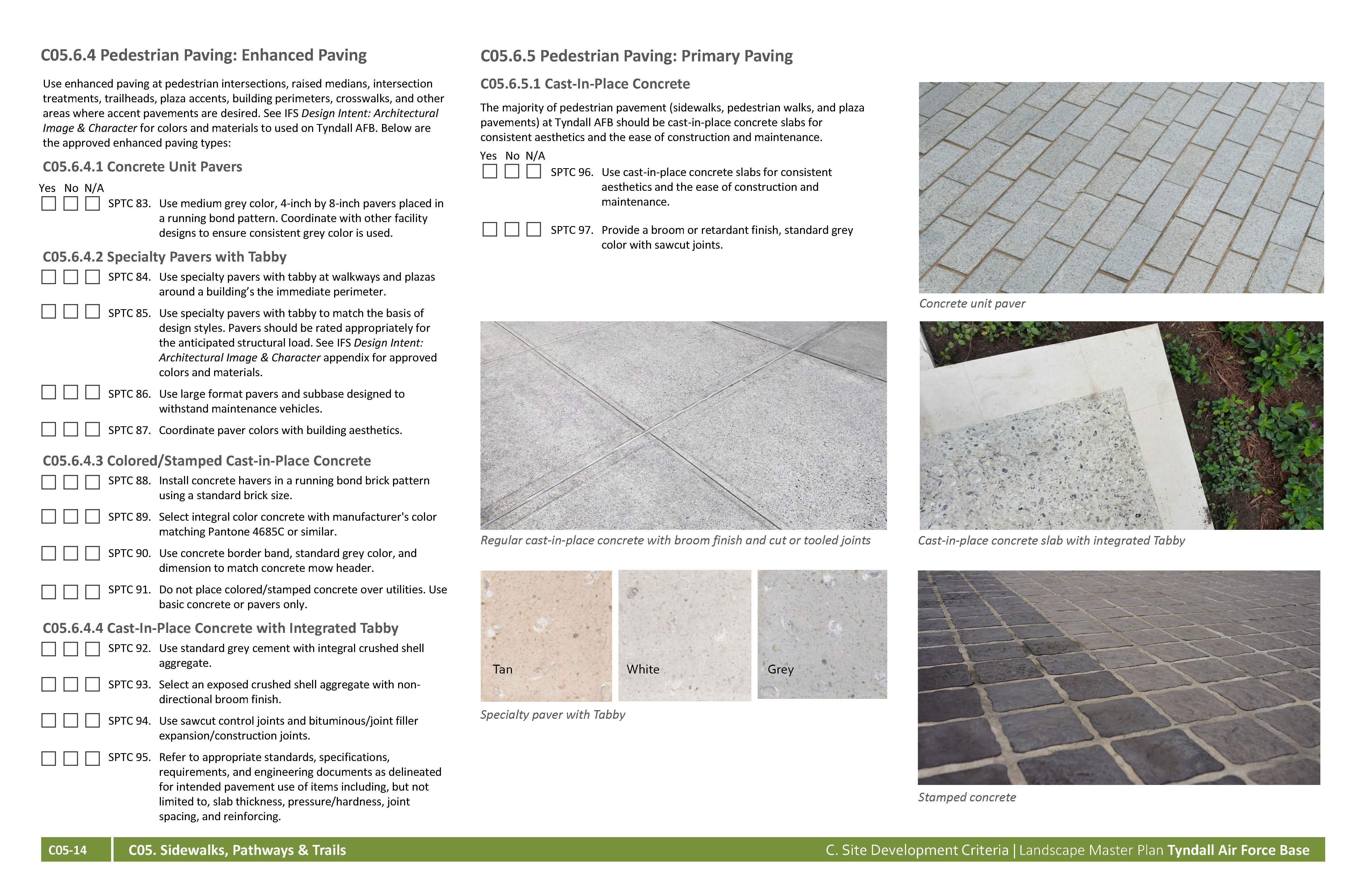
SPTC 83. Use medium grey color, 4-inch by 8-inch pavers placed in a running bond pattern. Coordinate with other facility designs to ensure consistent grey color is used.
Yes No NA
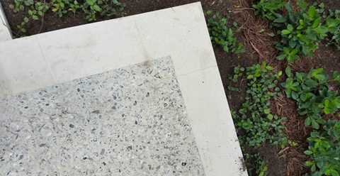
SPTC 84. Use specialty pavers with tabby at walkways and plazas around a building’s the immediate perimeter.
SPTC 85. Use specialty pavers with tabby to match the basis of design styles. Pavers should be rated appropriately for the anticipated structural load. See IFS Design Intent: Architectural Image & Character appendix for approved colors and materials.
SPTC 86. Use large format pavers and subbase designed to withstand maintenance vehicles.
SPTC 87. Coordinate paver colors with building aesthetics.
Yes No NA
SPTC 88. Install concrete havers in a running bond brick pattern using a standard brick size.
SPTC 89. Select integral color concrete with manufacturer's color matching Pantone 4685C or similar.
SPTC 90. Use concrete border band, standard grey color, and dimension to match concrete mow header.
SPTC 91. Do not place colored/stamped concrete over utilities. Use basic concrete or pavers only.
Yes No NA
SPTC 92. Use standard grey cement with integral crushed shell aggregate.
SPTC 93. Select an exposed crushed shell aggregate with non-directional broom finish.
SPTC 94. Use sawcut control joints and bituminous/joint filler expansion/construction joints.
SPTC 95. Refer to appropriate standards, specifications, requirements, and engineering documents as delineated for intended pavement use of items including, but not limited to, slab thickness, pressure/hardness, joint spacing, and reinforcing.
The majority of pedestrian pavement (sidewalks, pedestrian walks, and plaza pavements) at Tyndall AFB should be cast-in-place concrete slabs for consistent aesthetics and the ease of construction and maintenance.
Yes No NA
SPTC 96. Use cast-in-place concrete slabs for consistent aesthetics and the ease of construction and maintenance.
SPTC 97. Provide a broom or retardant finish, standard grey color with sawcut joints.
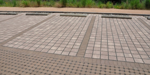
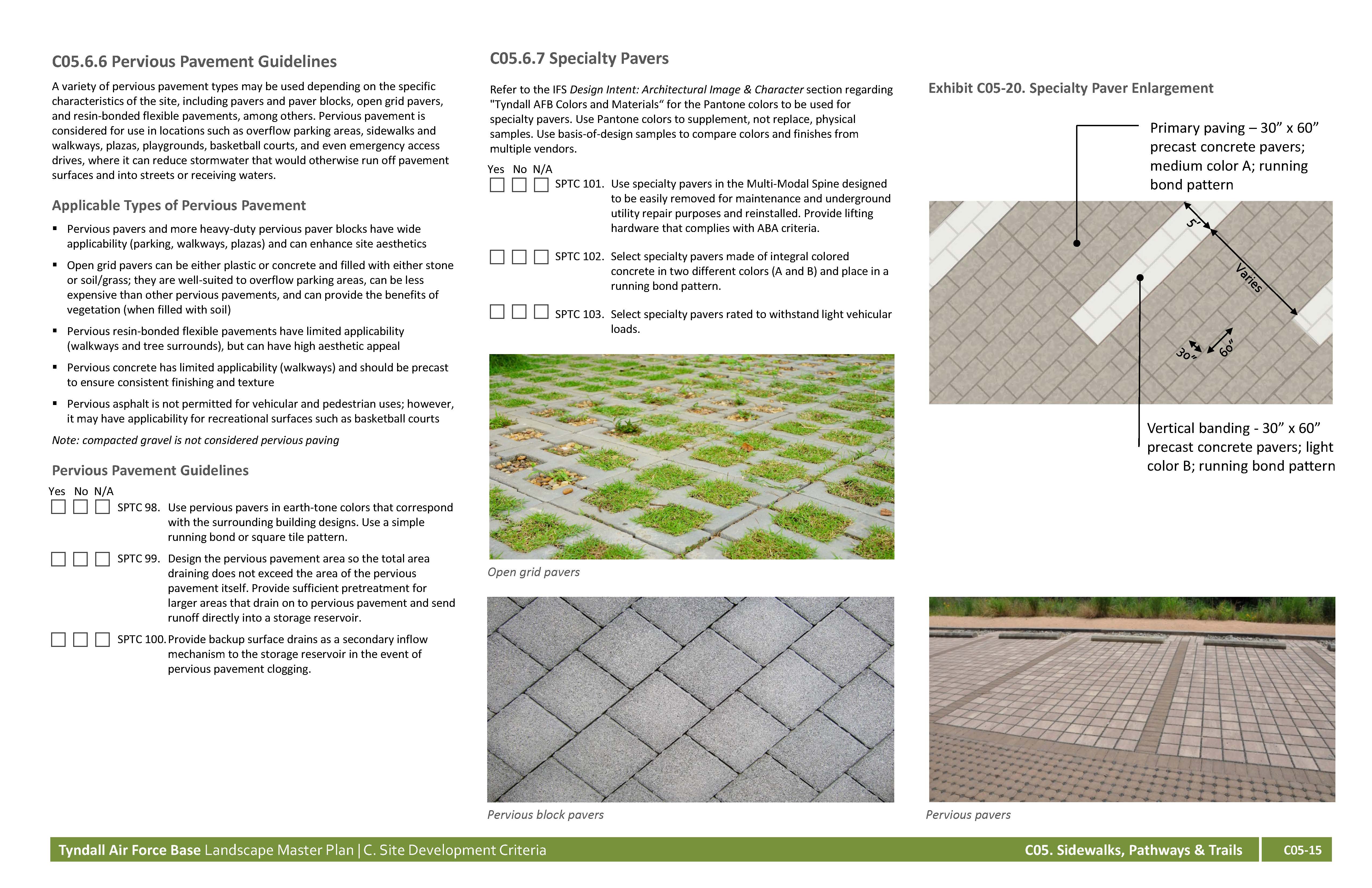
A variety of pervious pavement types may be used depending on the specific characteristics of the site, including pavers and paver blocks, open grid pavers, and resin-bonded flexible pavements, among others. Pervious pavement is considered for use in locations such as overflow parking areas, sidewalks and walkways, plazas, playgrounds, basketball courts, and even emergency access drives, where it can reduce stormwater that would otherwise run off pavement surfaces and into streets or receiving waters.
Applicable Types of Pervious Pavement
Note: compacted gravel is not considered pervious paving
Pervious Pavement Guidelines
Yes No NA
SPTC 98. Use pervious pavers in earth-tone colors that correspond with the surrounding building designs. Use a simple running bond or square tile pattern.
SPTC 99. Design the pervious pavement area so the total area draining does not exceed the area of the pervious pavement itself. Provide sufficient pretreatment for larger areas that drain on to pervious pavement and send runoff directly into a storage reservoir.
SPTC 100. Provide backup surface drains as a secondary inflow mechanism to the storage reservoir in the event of pervious pavement clogging.
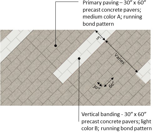
Refer to the IFS Design Intent: Architectural Image & Character section regarding "Tyndall AFB Colors and Materials“ for the Pantone colors to be used for specialty pavers. Use Pantone colors to supplement, not replace, physical samples. Use basis-of-design samples to compare colors and finishes from multiple vendors.
Yes No NA
SPTC 101. Use specialty pavers in the Multi-Modal Spine designed to be easily removed for maintenance and underground utility repair purposes and reinstalled. Provide lifting hardware that complies with ABA criteria.
SPTC 102. Select specialty pavers made of integral colored concrete in two different colors (A and B) and place in a running bond pattern.
SPTC 103. Select specialty pavers rated to withstand light vehicular loads.
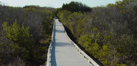
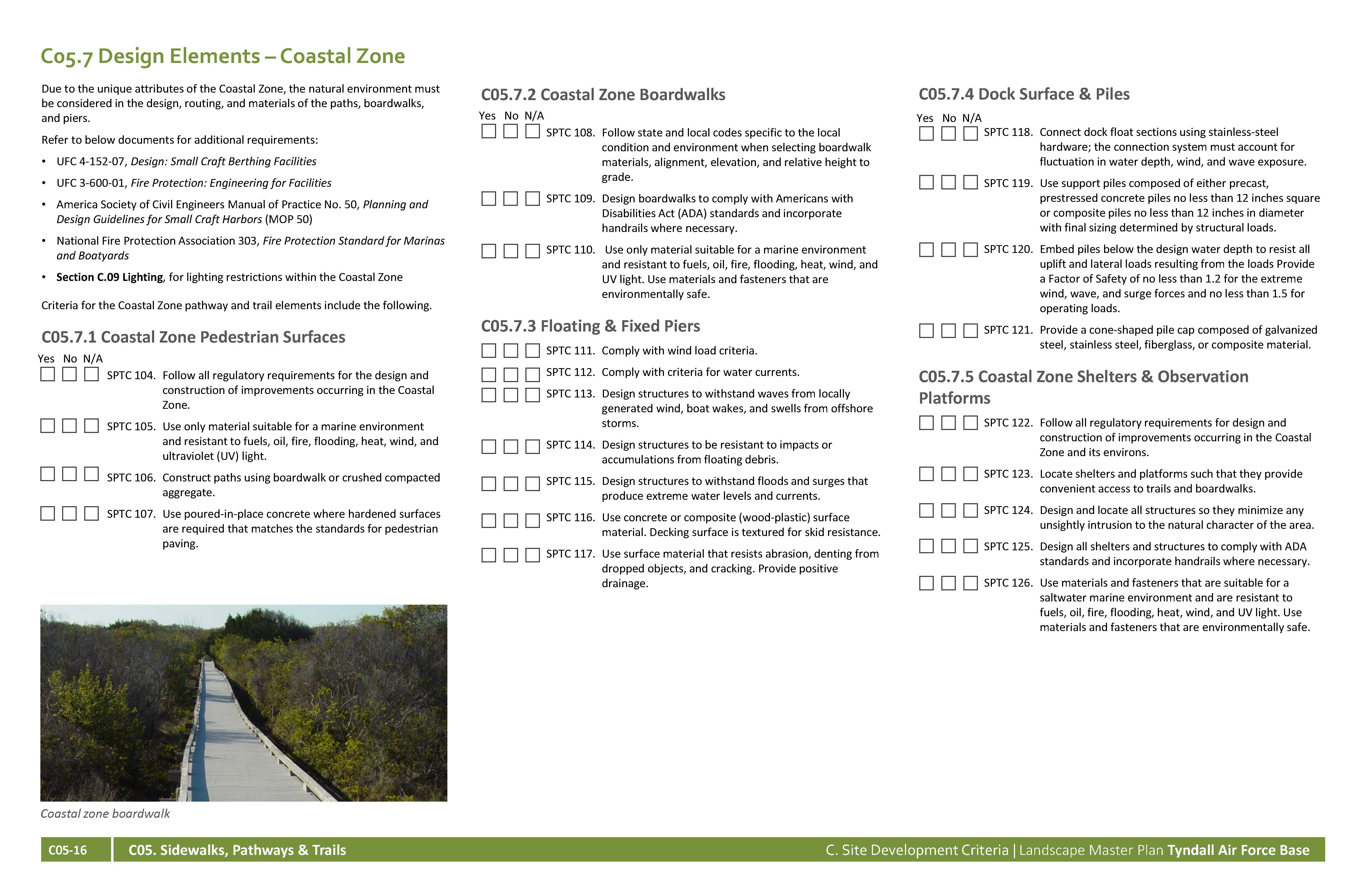
Due to the unique attributes of the Coastal Zone, the natural environment must be considered in the design, routing, and materials of the paths, boardwalks, and piers.
Refer to below documents for additional requirements:
Criteria for the Coastal Zone pathway and trail elements include the following.
Yes No NA
SPTC 104. Follow all regulatory requirements for the design and construction of improvements occurring in the Coastal Zone.
SPTC 105. Use only material suitable for a marine environment and resistant to fuels, oil, fire, flooding, heat, wind, and ultraviolet (UV) light.
SPTC 106. Construct paths using boardwalk or crushed compacted aggregate.
SPTC 107. Use poured-in-place concrete where hardened surfaces are required that matches the standards for pedestrian paving.
Yes No NA
SPTC 108. Follow state and local codes specific to the local condition and environment when selecting boardwalk materials, alignment, elevation, and relative height to grade.
SPTC 109. Design boardwalks to comply with Americans with Disabilities Act (ADA) standards and incorporate handrails where necessary.
SPTC 110. Use only material suitable for a marine environment and resistant to fuels, oil, fire, flooding, heat, wind, and UV light. Use materials and fasteners that are environmentally safe.
Yes No NA
SPTC 111. Comply with wind load criteria.
SPTC 112. Comply with criteria for water currents.
SPTC 113. Design structures to withstand waves from locally generated wind, boats wakes, and swells from offshore storms.
SPTC 114. Design structures to be resistant to impacts or accumulations from floating debris.
SPTC 115. Design structures to withstand floods and surges that produce extreme water levels and currents.
SPTC 116. Use concrete or composite (wood-plastic) surface material. Decking surface is textured for skid resistance.
SPTC 117. Use surface material that resists abrasion, denting from dropped objects, and cracking. Provide positive drainage.
Yes No NA
SPTC 118. Connect dock float sections using stainless-steel hardware; the connection system must account for fluctuation in water depth, wind, and wave exposure.
SPTC 119. Use support piles composed of either precast, prestressed concrete piles no less than 12 inches square or composite piles no less than 12 inches in diameter with final sizing determined by structural loads.
SPTC 120. Embed piles below the design water depth to resist all uplift and lateral loads resulting from the loads Provide a Factor of Safety of no less than 1.2 for the extreme wind, wave, and surge forces and no less than 1.5 for operating loads.
SPTC 121. Provide a cone-shaped pile cap composed of galvanized steel, stainless steel, fiberglass, or composite material.
Yes No NA
SPTC 122. Follow all regulatory requirements for design and construction of improvements occurring in the Coastal Zone and its environs.
SPTC 123. Locate shelters and platforms such that they provide convenient access to trails and boardwalks.
SPTC 124. Design and locate all structures so they minimize any unsightly intrusion to the natural character of the area.
SPTC 125. Design all shelters and structures to comply with ADA standards and incorporate handrails where necessary.
SPTC 126. Use materials and fasteners that are suitable for a saltwater marine environment and are resistant to fuels, oil, fire, flooding, heat, wind, and UV light. Use materials and fasteners that are environmentally safe.